When I recently connected my Rode NT1-A to my Focusrite Scarlett 2i2 1st Gen after a very long time I noticed some oddities in the recorded waveforms.
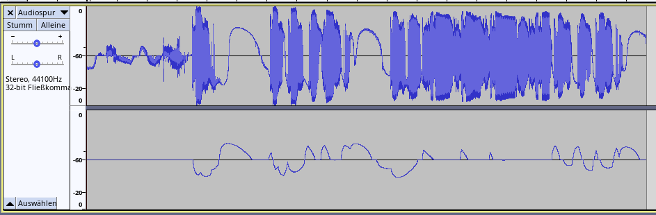
As you can see the waveform of the microphone shows a hugely changing DC offset as well as heavy crosstalk to the other channel that was not even connected to anything at all.
So I opened it up following this post and was surprised that the PCB looked quite different despite it being the same generation. Apparently there are different internal revisions inside the same generation. I managed to find a tear down blog post in Japanese having the same PCB as mine does.
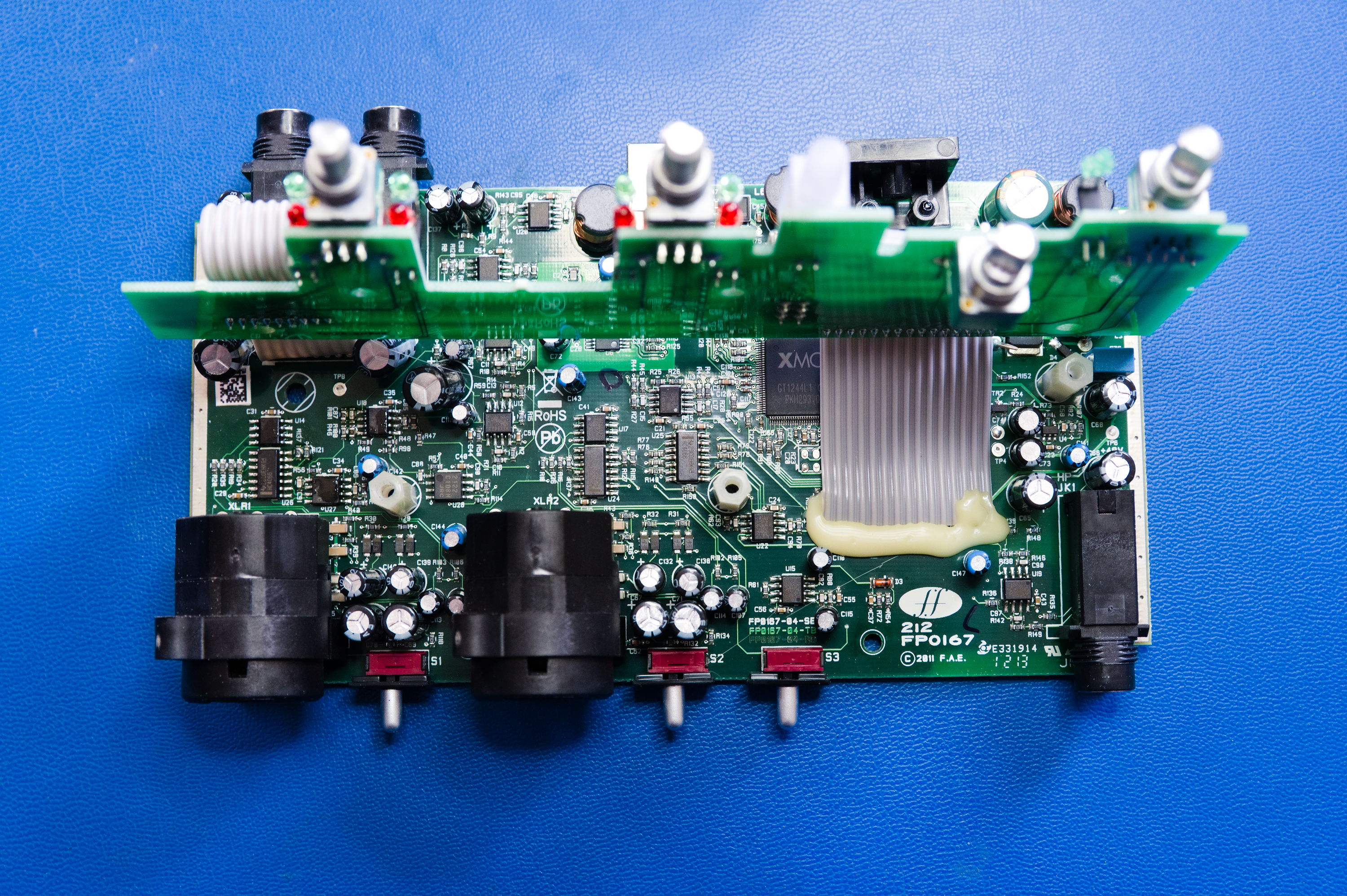
Then I checked what circuits are shared between both channels and quickly found the voltage regulator for all the op-amps (U4). This revision uses only one positive power rail which makes it easier to debug.
When measuring the voltage I found that there was almost no difference between input and output so regulation was not happening since every linear regulator needs at least some dropout voltage difference. The regulator used is a MIC5205 that needs typically 140mV dropout voltage at 100mA current according to the datasheet.
Since it is an adjustable regulator the voltage is set via a voltage divider. One of the resistors gave strange resistance readings to I swapped it with two other resistors in parallel since I did not have the exact value of the broken resistor in stock.
This indeed fixed the problem with the missing voltage regulation and the voltage for the op-amps was now at at super stable 4.5V which gives enough room for regulation since the USB input voltage does not drop much below 4.9V with a proper cable.
With dynamic microphones the crosstalk was now completely gone. My Rode NT1-A on the other hand, which is a condenser microphone, still showed a strange dynamic DC offset.
So what is the difference between dynamic and condenser microphones? Of course it is the need for phantom power of the latter.
I measured the 48V phantom power which gave a 46V reading without a microphone connected. This is right inside the specification for this but when I connected the microphone the voltage dropped to only about 32V which is way too low!
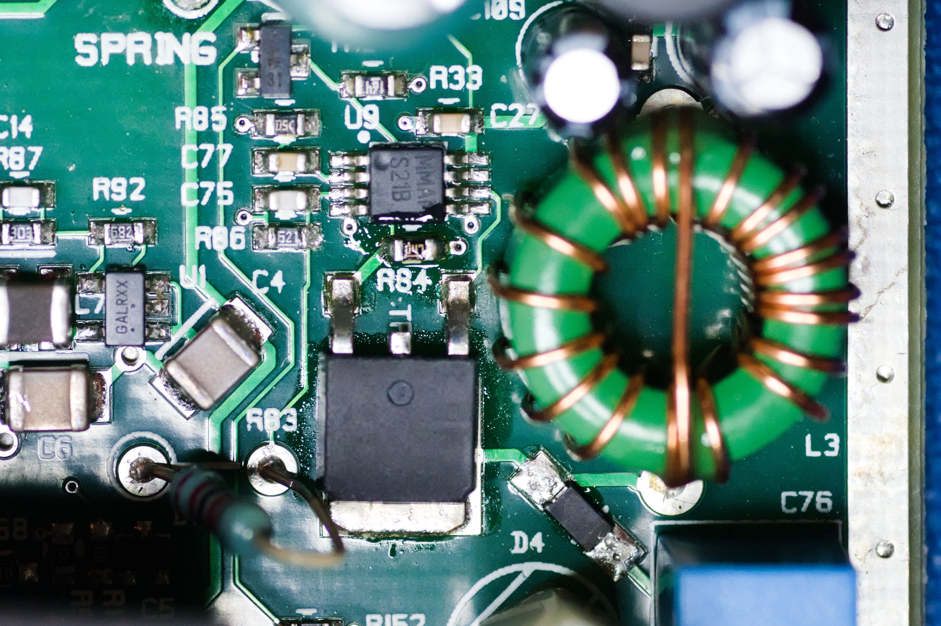
The boost-converter used is the LM3488 with the same circuit as in the datasheet on page 18. It uses a sense resistor which acts as a current limiter. You can see it in the picture as R84. It is 0.36 Ohms and with an oscilloscope connected to it I could confirm that the limit was reached when the NT1-A was attached. In my opinion this is clearly a design flaw!
I soldered a 0.48 Ohms resistor on top effectively raising the current threshold but this was not enough to keep the voltage stable during use. Since all my condenser microphones are also ok with 24V phantom power I decided to convert the circuit. R83 and R86 form a voltage divider that sets the output voltage. I changed R86 to 1.1 kOhms that resulted in a voltage of around 26V. The phantom power now stays stable as well!
The last thing to do was to change the phantom power output resistors (R1 and R2 in this schematic) to the correct value for 24V which is 1.2 kOhms. The exact value is not that important but what is important is that the two resistors for each channel are very close to each other (according to IEC 61938 within 0.1%!). Since I only have 1.1 kOhms with an accuracy of 5% I had to improvise again. The good thing when you are just fixing your own stuff for fun you can spend as much effort as you like. So I took 10 resistors from the tape and looked for the most similar ones. In the end I managed to find two pairs that fell within 1 Ohm according to my multimeter.
So with all the modifications I could get rid of the crosstalk and can be sure that the phantom power is stable. The changing DC offset got better but seems to be inherent to my NT1-A since it is also present using another audio interface. But this is not a big problem since the DC (and sub-sonic) part can perfectly be removed in post processing.
I am very happy with the result, learned a lot and had some great fun while reverse engineering and tinkering.

Comments
July 25, 2022 23:15
@DerFetzer looking online, it really seems that the 2i2 1st gen had completely insufficient phantom current available for many mics, or at least a design flaw that made that happen in a fair number of them.